Designing a Custom DIN Rail Mount with an AI CAD Agent

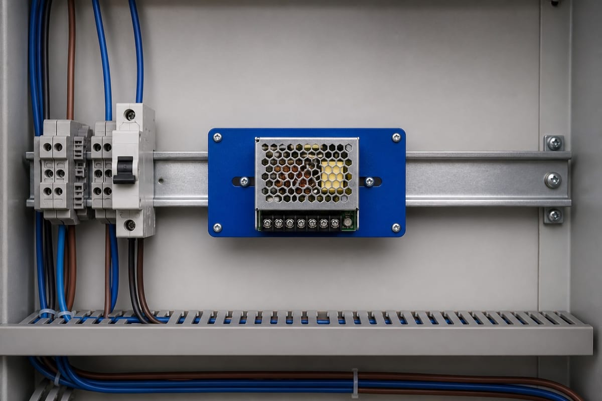
Every electronics project eventually hits the same wall: you have a component that needs to go on a DIN rail, and the manufacturer never made an adapter for it. Ours was a Thor RPS-400-TF power supply with four M3 mounting holes and no rail clip of any kind.
This is the least glamorous category of CAD work in existence — a flat plate with four holes in exactly the right places — and it's also the category where an AI CAD agent earns its keep, because "exactly the right places" is the entire job.
Here's the real session, all four prompts of it, including the part where the first print didn't fit.
You can open the finished design here — the full conversation, the parametric source, and the 3D preview are all public.
Why not just generate a mesh?
Worth addressing up front, because it's the most common wrong turn. AI mesh generators — including our own — are excellent at organic and decorative shapes. They are the wrong tool here.
A generated mesh is a shape. This part is a set of measurements: four holes on a 119.74 × 49.73 mm pattern, a channel that captures a 35 × 7.5 mm rail, an M3 clearance hole that has to actually clear an M3 screw. Miss any of those by half a millimetre and you've printed a coaster.
That's the job for the CAD Agent, which writes real parametric CAD instead of sculpting geometry.
What we gave it
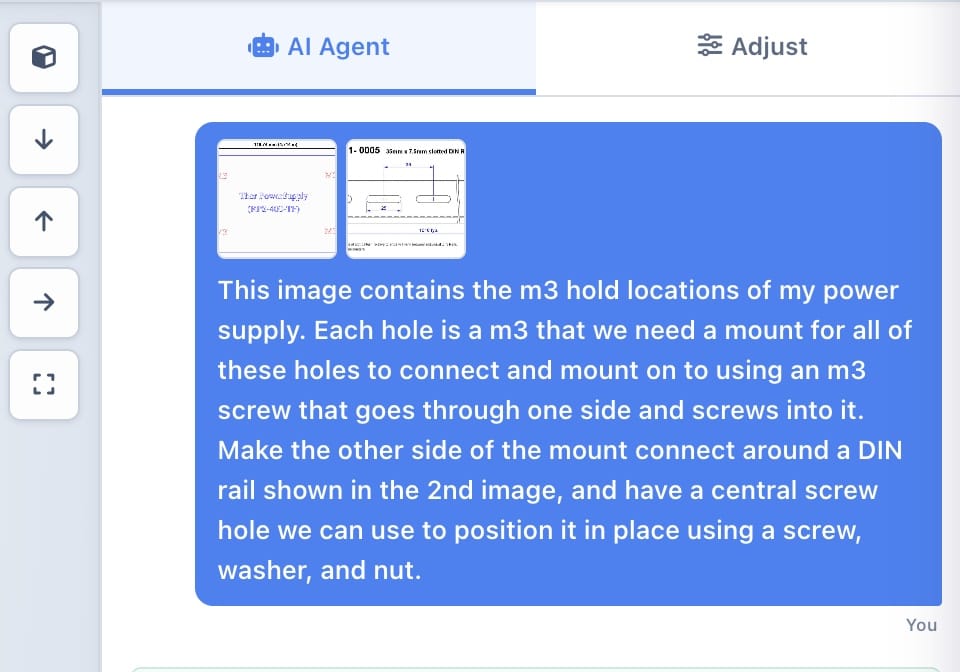
Two reference images and one paragraph. The images were dimensioned drawings — one of the power supply showing its M3 hole locations, one of a standard top-hat DIN rail.
This matters more than the prompt wording. A photo of an object tells the agent what something looks like. A dimensioned drawing tells it how big everything is, and it will read the numbers off the drawing. If you have a datasheet for your part, use the drawing from it.
The opening prompt, verbatim:
This image contains the m3 hold locations of my power supply. Each hole is a m3 that we need a mount for all of these holes to connect and mount on to using an m3 screw that goes through one side and screws into it. Make the other side of the mount connect around a DIN rail shown in the 2nd image, and have a central screw hole we can use to position it in place using a screw, washer, and nut.
Typos and all. It doesn't need to be tidy — it needs to say what the part has to do.
What came back first
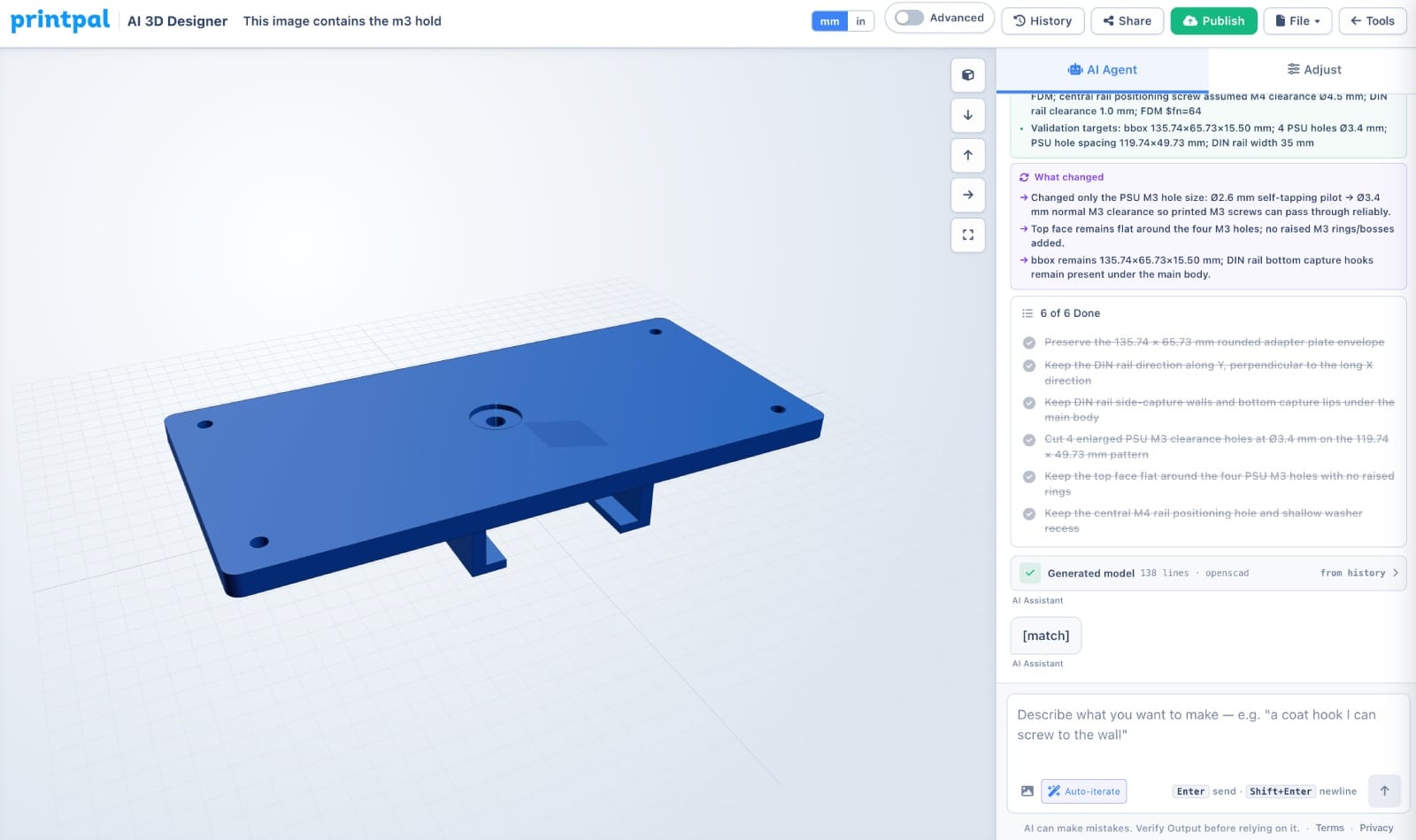
Before writing any geometry, the agent produced a brief and a build plan checklist — a short contract stating what it thinks it's making. That's the thing to read carefully, because it's cheaper to correct an assumption than a model:
Envelope: 135.74 × 65.73 × 16.00 mm Defaults adopted: M3 self-tapping pilot holes Ø2.6 mm; central rail positioning screw assumed M4 clearance Ø4.5 mm; 8 mm perimeter margin; cosmetic R3 corners
Note the word assumed. We never said what size the central screw was, so it picked M4, said so out loud, and moved on. That's the right behavior — flag the guess rather than silently bury it.
Then it wrote the dimensions it had read off the drawings into the top of the code as comments:
// === Dimensions extracted from reference drawing ===
// psu_hole_spacing_x        = 119.74 mm  (power supply drawing, horizontal M3 spacing)
// psu_hole_spacing_y        = 49.73  mm  (power supply drawing, vertical M3 spacing)
// din_rail_width            = 35.00  mm  (DIN rail drawing, overall rail face width)
// din_rail_depth            = 7.50   mm  (DIN rail drawing, top-hat rail depth)
// din_rail_slot_length      = 25.00  mm  (DIN rail drawing, elongated slot length)
// din_rail_slot_width       = 5.20   mm  (DIN rail drawing, elongated slot width)
// din_rail_slot_pitch       = 36.00  mm  (DIN rail drawing, distance between slot centers)
Check this block before you check anything else. It's the agent showing its work. Every downstream dimension is derived from these seven numbers, so if it misread the drawing, this is where you catch it in five seconds instead of after a four-hour print.
Fix 1: wrong orientation
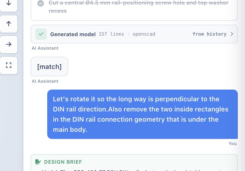
The first render had the rail clip running along the plate's long axis, which would have mounted the power supply lengthwise down the rail instead of across it. Also, there were two stray rectangular pads under the body.
Let's rotate it so the long way is perpendicular to the DIN rail direction. Also remove the two inside rectangles in the DIN rail connection geometry that is under the main body.
No coordinates, no axis names — just the change in plain language. The agent rotated the underside clip so the rail runs along Y, perpendicular to the 135.74 mm long axis, and reported that the outer bounding box hadn't changed because only the underside was affected.
Fix 2: put back the part we actually needed
This is the honest bit that a polished demo would edit out. "Remove the two inside rectangles" removed slightly too much — the bottom capture lips went with them, and without those the plate would just rest against the rail instead of hooking around it. The raised bosses around the M3 holes were also unwanted, since the power supply needs to sit flat.
Add back in the geometry of the DIN rail clip that goes around the bottom of the din rail. Also on the m3 holes, remove the lifted rings around the holes on the top face, so the top face is flat
Two unrelated corrections in one message, and it handled both. It also reported the consequence without being asked:
bbox current 135.74×65.73×16 mm → new target 135.74×65.73×15.5 mm; height drops 0.5 mm overall because the 2.5 mm top bosses are removed while the DIN bottom-hook space is added underneath the plate.
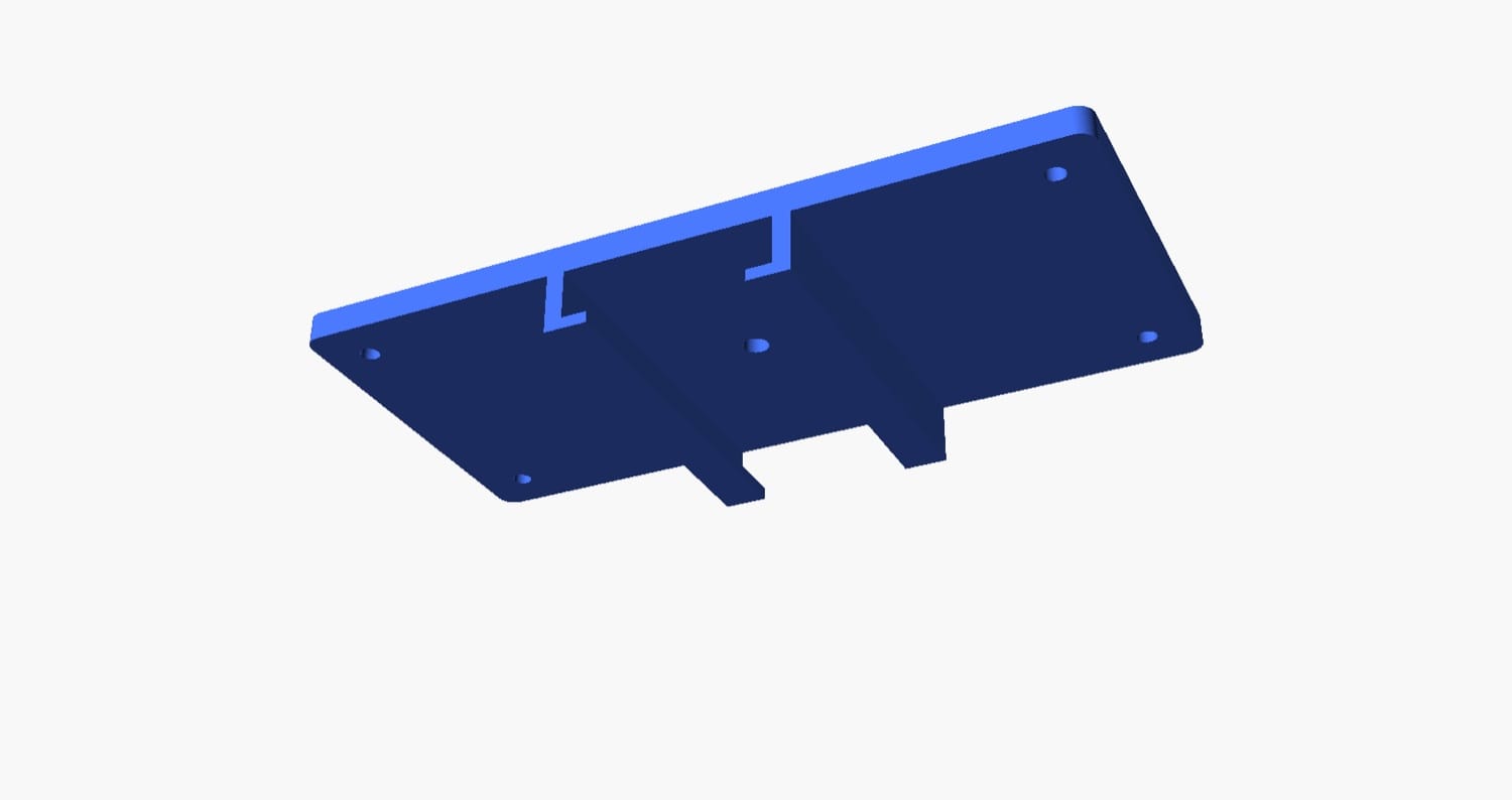
Here's the resulting cross-section — the 5 mm plate on top, two 3 mm capture walls, and the 2 mm lips that hook under the rail edges:

And from underneath, with the channel running perpendicular to the long axis:
Fix 3: the one only a printer could find
Everything looked right. We printed it. The screws wouldn't go in.
make the m3 holes slighty larger because when i 3d print this part and try to put m3s through it doesnt go and doesnt even thread through either
The agent had chosen Ø2.6 mm, the correct pilot size for an M3 screw cutting its own thread into plastic. But this plate is a clearance part — the screw passes through it and threads into the power supply on the other side. Those are different holes:
| Hole type | M3 diameter | Use |
|---|---|---|
| Self-tapping pilot | Ø2.5–2.6 mm | Screw cuts threads into the plastic |
| Normal clearance | Ø3.4 mm | Screw passes freely through |
| Loose clearance | Ø3.6 mm | Passes through with alignment slop |
It changed one number and left everything else alone:
Changed only the PSU M3 hole size: Ø2.6 mm self-tapping pilot → Ø3.4 mm normal M3 clearance so printed M3 screws can pass through reliably.
Two things worth taking from this. First, FDM printing shrinks holes — a nominally perfect hole prints undersized, which is why 3.4 mm rather than 3.1 mm. Second, and more useful: print a test piece early. The three prompts before this one were fixing things we could see on screen. This one fixed something no amount of staring at a render would have revealed.
The finished part
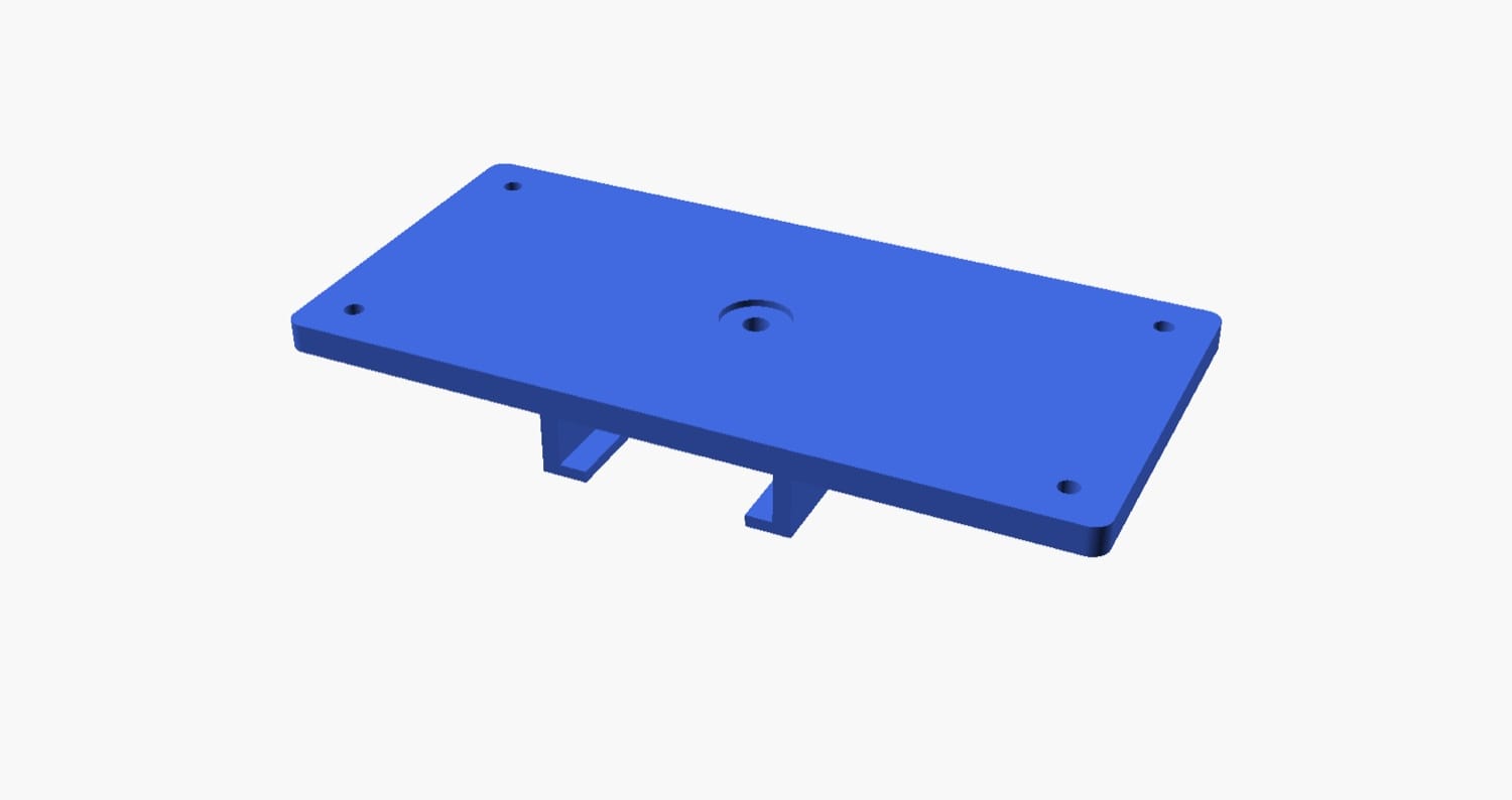
| Bounding box | 135.74 × 65.73 × 15.50 mm |
| Volume | 49.52 cm³ (roughly 62 g in PLA) |
| PSU holes | 4 × Ø3.4 mm on a 119.74 × 49.73 mm pattern |
| Central fixing | Ø4.5 mm with a Ø12 × 1.2 mm washer recess |
| Rail capture | 35 mm nominal, 1.0 mm clearance, 3 mm walls, 2 mm hook lips |
| Face plate | 5 mm |
At ~62 g this isn't a trivial print — worth running through the 3D Print Cost Calculator before you commit. Print it face-down so the flat mounting surface comes off the smooth build plate: the only overhangs are the two 4.5 mm inward hook lips at the top of the walls, which want a small amount of support. PETG is the better material choice over PLA here, since control cabinets get warm.
You get sliders, not a dead file
The most important output isn't the STL. It's that the agent hoisted the driving dimensions into named parameters at the top of the file:
// Power-supply M3 hole spacing in X
psu_hole_spacing_x = 119.74;

// M3 clearance hole diameter for PSU screws
m3_pilot_diameter = 3.4;

// Nominal width of standard top-hat DIN rail
din_rail_width = 35;
That comment above each variable becomes its label in the Parameters panel, so every one of those numbers is a slider in the interface. Different power supply? Change two numbers. Screws still tight? Nudge the hole diameter and re-export — no CAD, no rebuild, no re-prompting.
The agent also tags features in the code with @feature: markers — din_rail_slide_clip, central_washer_recess, and so on — which show up as chips you can @-mention in follow-up prompts to point at a specific piece of geometry rather than describing it.
Anything the agent left as an internal constant rather than a top-level parameter won't appear as a slider. If you want one exposed, just ask for it.
What transfers to your project
Four prompts, one failed test print, one working bracket. The method generalizes to basically any adapter, mount, or enclosure:
- Feed it a dimensioned drawing, not a photo. Datasheet drawings with labeled dimensions produce dramatically better first attempts than photos of the object.
- Read the brief before the render. The "defaults adopted" line is where the agent tells you what it guessed. Correcting an assumption costs one sentence.
- Verify the extracted-dimensions block. Everything else derives from those numbers.
- One change per message, in plain English. "Rotate it so the long way is perpendicular to the rail" works. There's no need to learn a command vocabulary.
- Print early, at draft quality. Screen geometry can't tell you a hole is too tight.
- Know your clearance sizes. Pilot holes and clearance holes are different holes, and the agent can't tell which you want unless you say whether the screw threads in or passes through.
Try it
The finished design is public: DIN rail PSU adapter on PrintPal.
If you've got a component sitting loose in an enclosure right now, take a photo of its datasheet drawing and describe the bracket you need. Four prompts is a realistic budget.