Build a Live Plane Radar on a Round ESP32

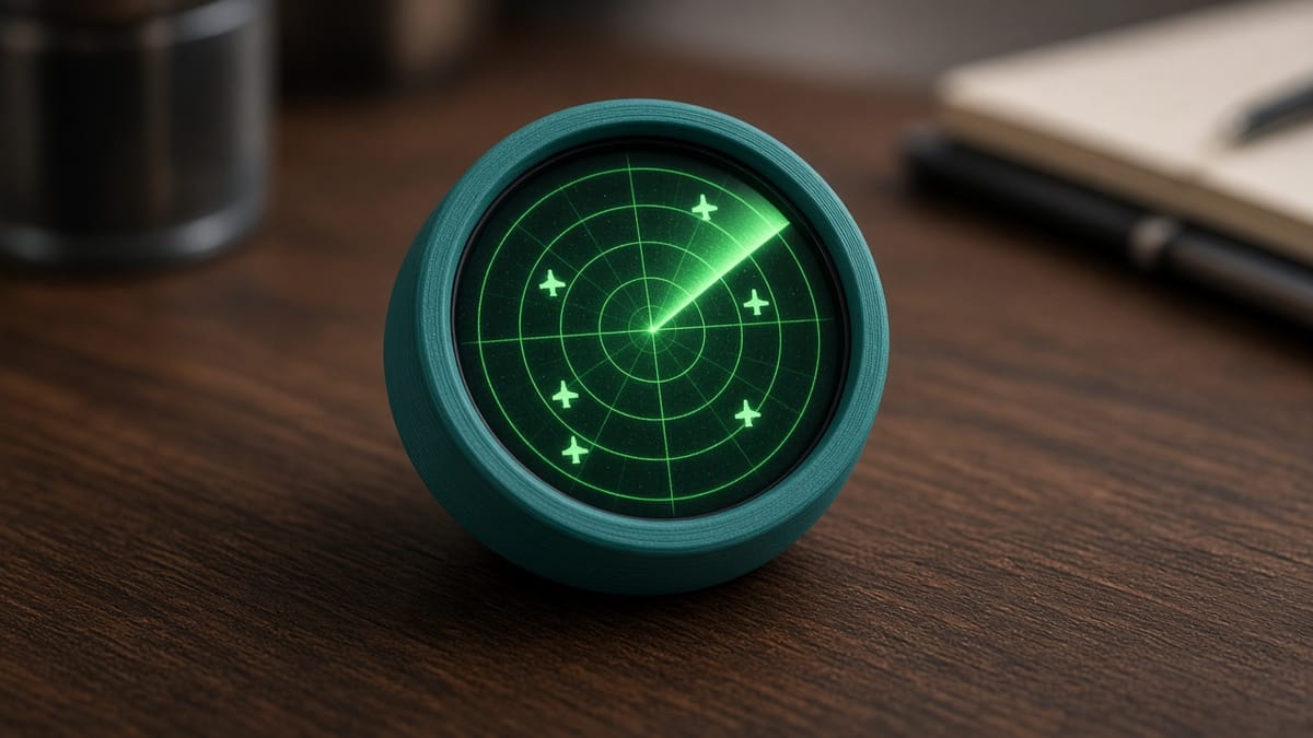
You sit in the middle of a green circle. Airplanes show up as little triangles, each one pointing the way it is flying, with a callsign like UAL182 beside it. That circle is a real ESP32 plane radar, small enough to live on a desk.
The board is the Waveshare ESP32-S3-Touch-LCD-1.28 (Amazon B0CM68M8LR), the PrintPal Desk Pal puck. It is a round 240×240 GC9A01 screen, about 39 mm across, with touch, a motion sensor, and USB-C. The full case, firmware, and flash button are on the Desk Pal plane radar project.
The chip asks a website a question
Planes already announce where they are. A public feed, opendata.adsb.fi, collects those ADS-B messages. ADS-B is the radio shout a plane makes: who I am, where I am, which way I am heading, how fast.
Your puck cannot hear that airplane radio. It uses ordinary Wi-Fi to ask the website, “what planes are near this latitude and longitude?” That ask is an HTTP GET. The answer comes back as JSON, a packing list the program can read. One plane looks roughly like this: a callsign, a latitude, a longitude, a heading called track, and a speed called gs.
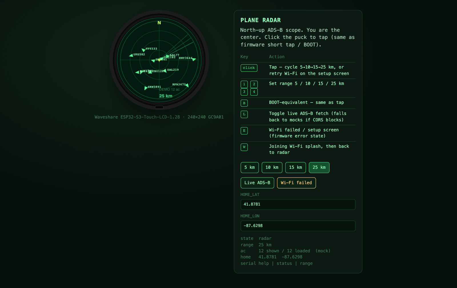
The download always covers a 25 km circle. Tapping the glass, or a short press of BOOT, only changes the picture: 5 → 10 → 15 → 25 km. Zooming in does not start a new download. If Wi-Fi fails or the feed is empty, the scope still draws demo traffic, so you can learn the screen before the live data works.
The ask happens on a background task. The sweep keeps moving while the mailbox is being checked. If the program waited for the website on the same to-do list as the drawing, the radar would hitch every time it refreshed.
Wi-Fi on this board is 2.4 GHz only
The ESP32-S3 in this puck has a 2.4 GHz radio. It cannot join a 5 GHz-only network. School guest Wi-Fi is a common miss. If the screen sits on “joining Wi-Fi,” use the 2.4 GHz name of your home router.
At the top of the sketch, four labeled boxes (#define) hold your network name, password, and home latitude and longitude. The published file uses placeholders (YOUR_WIFI_SSID_HERE). Until you edit those and flash again, the puck stays on a setup screen on purpose. It will not try to join a fake network. Search “my latitude longitude” and paste the two numbers. West longitudes are negative.
From the Earth to the round screen
Latitude is north and south. Longitude is east and west. The screen is x (right) and y (down). The program measures how far each plane is from your home point, and which compass direction that is. North is up. Distance from the center is how far the plane is from you. A triangle at the edge of the 10 km zoom is about 10 km away.
Flash it
Use Chrome or Edge on a computer, not Safari and not a phone. Plug in a data USB-C cable (some cables only charge). Open the plane radar project and use Flash to board. If no port appears, hold BOOT, tap RESET, and release BOOT. Windows and some Macs need the WCH CH34x driver for this board’s USB chip.
To change the code later, use Arduino IDE as ESP32S3 Dev Module, OPI PSRAM, 16 MB flash, USB CDC On Boot. The display setup must include USE_HSPI_PORT. Without that one flag, the round GC9A01 stays black. Serial is 115200. Type help, then status. status tells you whether the triangles are live or demo. range 10 sets the zoom.
Print the snap-fit shell face-down in PLA or PETG, 0.2 mm layers. The cavity is keyed. USB-C sits at the bottom. Do not force the puck in backwards.
That is the whole build: a round screen, a question sent over 2.4 GHz Wi-Fi, and a bit of geometry that turns latitude and longitude into a dot on a circle.