How to Turn Any 3D Model Into a Flexi Print With the Articulated Model Creator

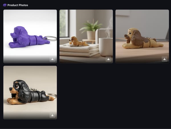
Flexi and articulated prints are some of the most popular items on Etsy and social media right now. Flexible dragons, articulated sharks, posable figurines, and fidget toys all rely on the same concept: a rigid model split into segments connected by snap-fit or print-in-place joints.
The problem is that making these models traditionally requires solid CAD skills. You need to know how to perform boolean operations, align joint geometry, and export clean manifold meshes. That puts most sellers and hobbyists out of the game.
PrintPal's Flexi Model Creator changes that. Upload any STL, click where you want joints, and export a cut model ready to print. Everything runs in your browser with no software to install. Here is how to use it step by step.
What You Need Before Starting
All you need is an STL file of the model you want to make flexible. This can be something you designed, downloaded from a model-sharing site, or generated with an AI tool. The model should be a single solid body. Models that are already split into multiple parts may not work as expected since the tool performs boolean cuts on the loaded geometry. Watertight (manifold) meshes produce the best results. Most STL files from reputable sources are already manifold, but if you run into export errors, try running your model through a mesh repair tool first.
Step 1: Upload Your Model
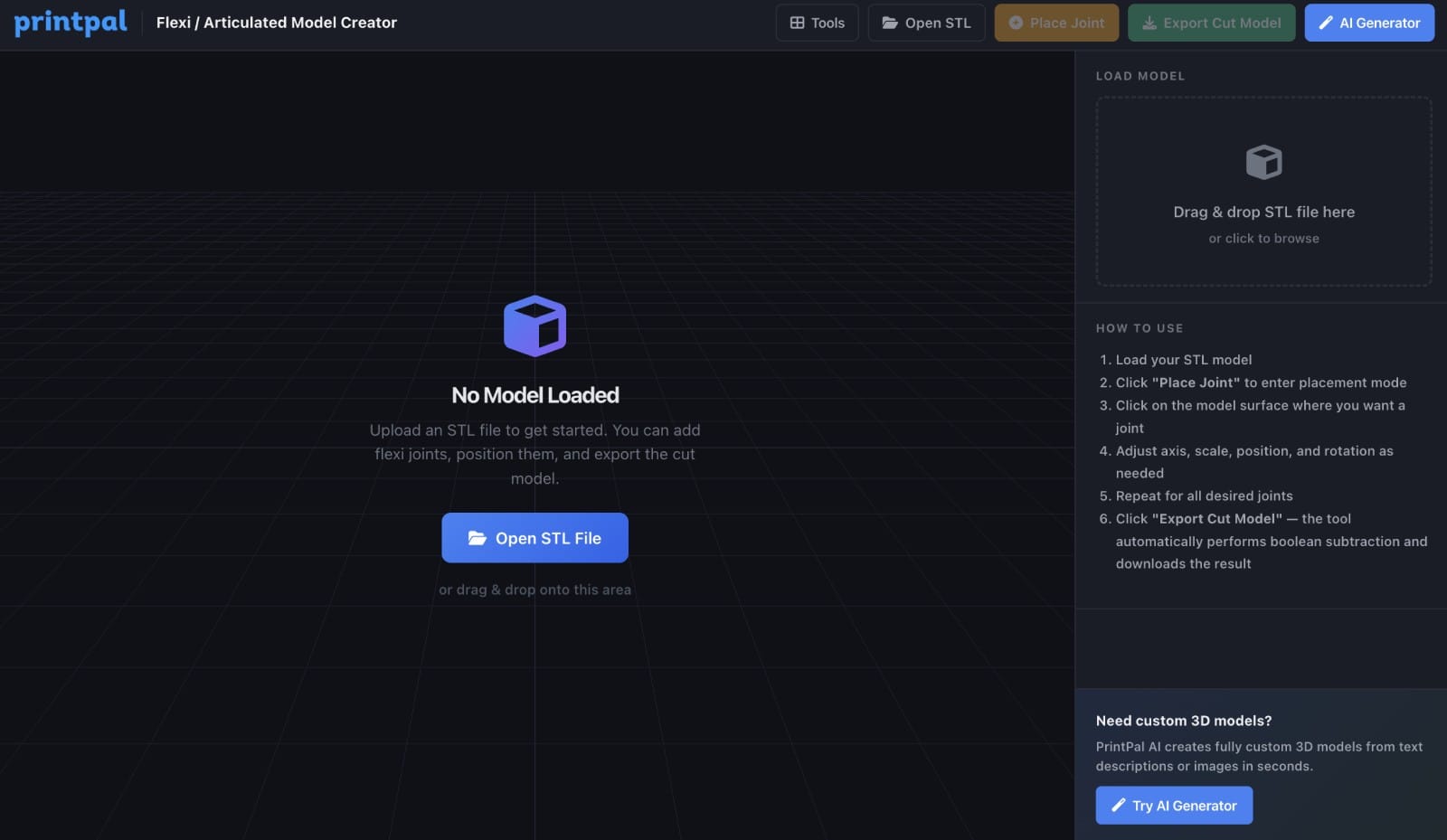
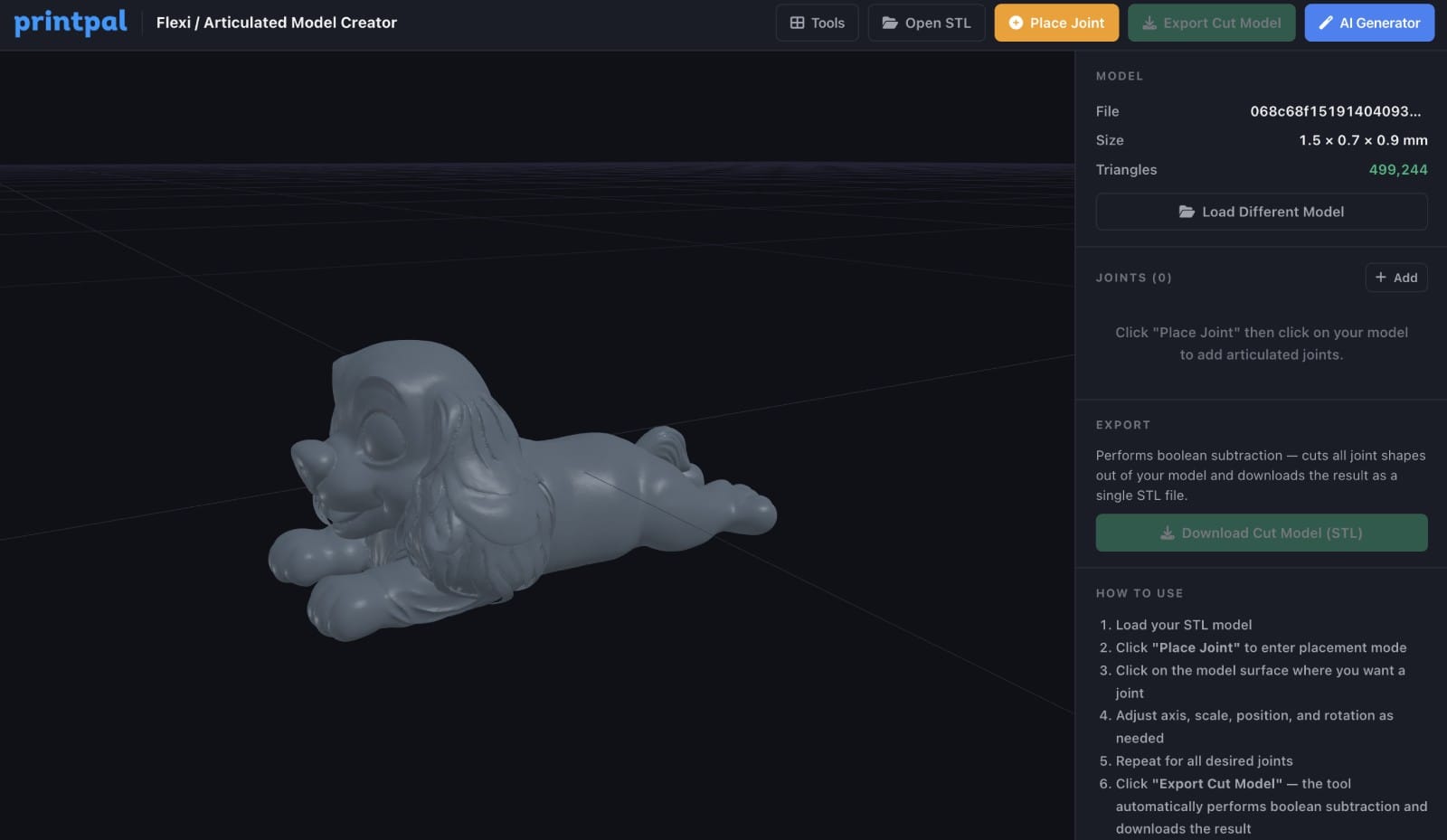
Go to printpal.io/tools/flexi-model-creator and click the "Upload Model" button in the center of the 3D viewer, or use the file input in the sidebar.The tool accepts STL files. Once loaded, your model appears in the 3D viewer. You can orbit, zoom, and pan to inspect it from any angle.The sidebar shows your model info: file name, dimensions, and triangle count.
Step 2: Enter Placement Mode
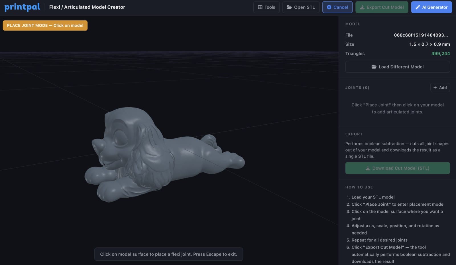
Click the "Place Joint" button in the sidebar under the Joints section. This activates placement mode. Your cursor changes and the tool waits for you to click on the surface of your model. While in placement mode, a single click on the model surface places a flexi joint cutter at that location.
Step 3: Place Your First Joint
Click on the surface of your model where you want the first articulation point. Common locations include:
- Neck joints on animals and figurines
- Between body segments on dragons, snakes, and fish
- Limb connections on action figures
- Any point where you want rotational movement
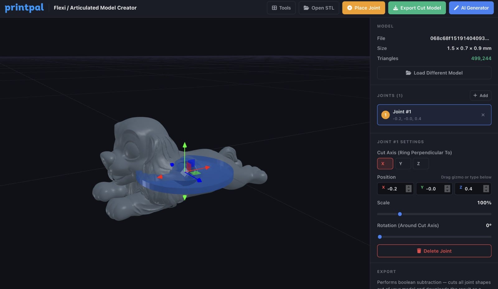
When you click, the cutter appears on your model as a semi-transparent orange ring. The tool automatically sizes the cutter to match the cross-section of your model at that point.
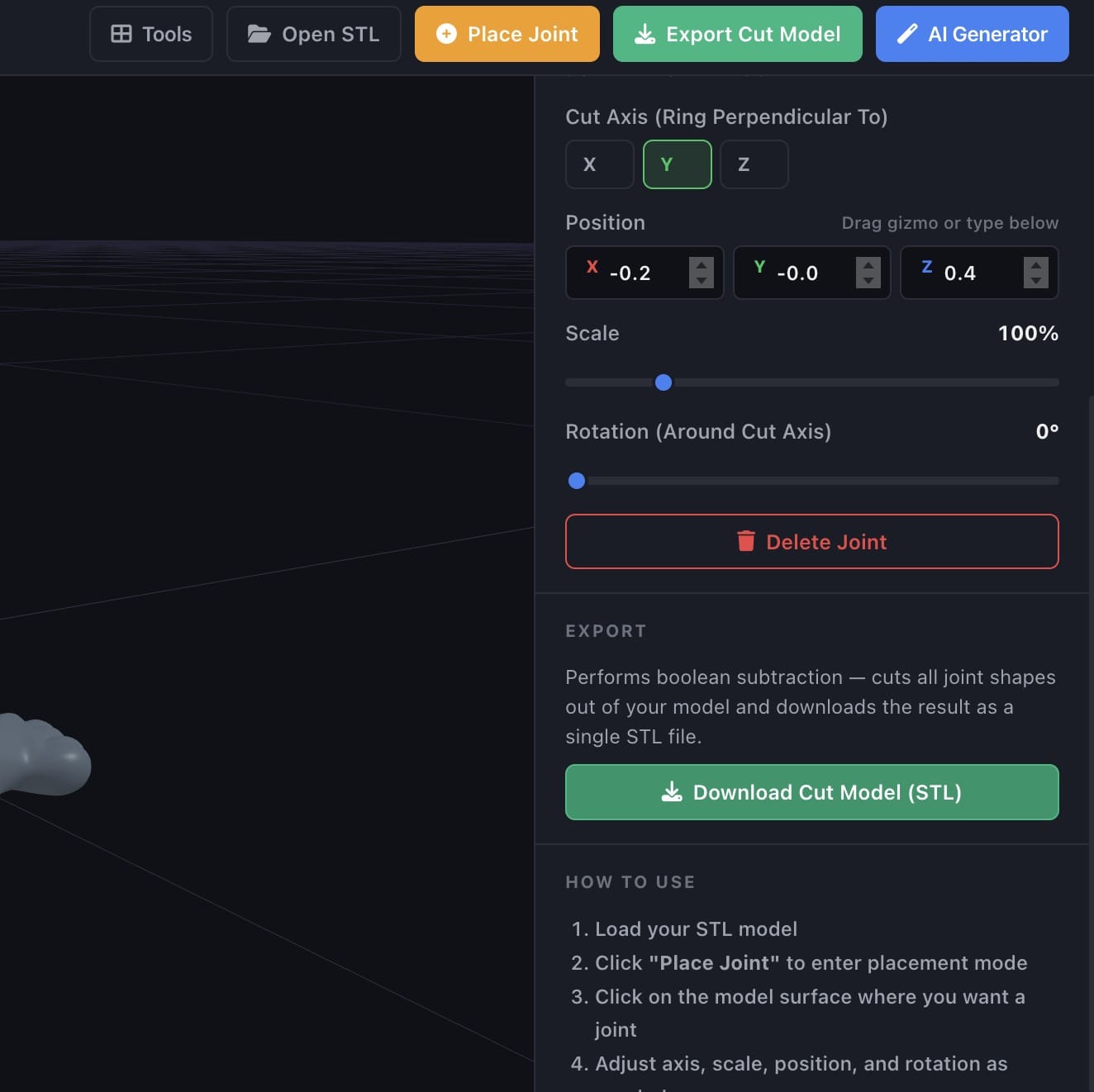
Step 4: Choose the Cut Axis
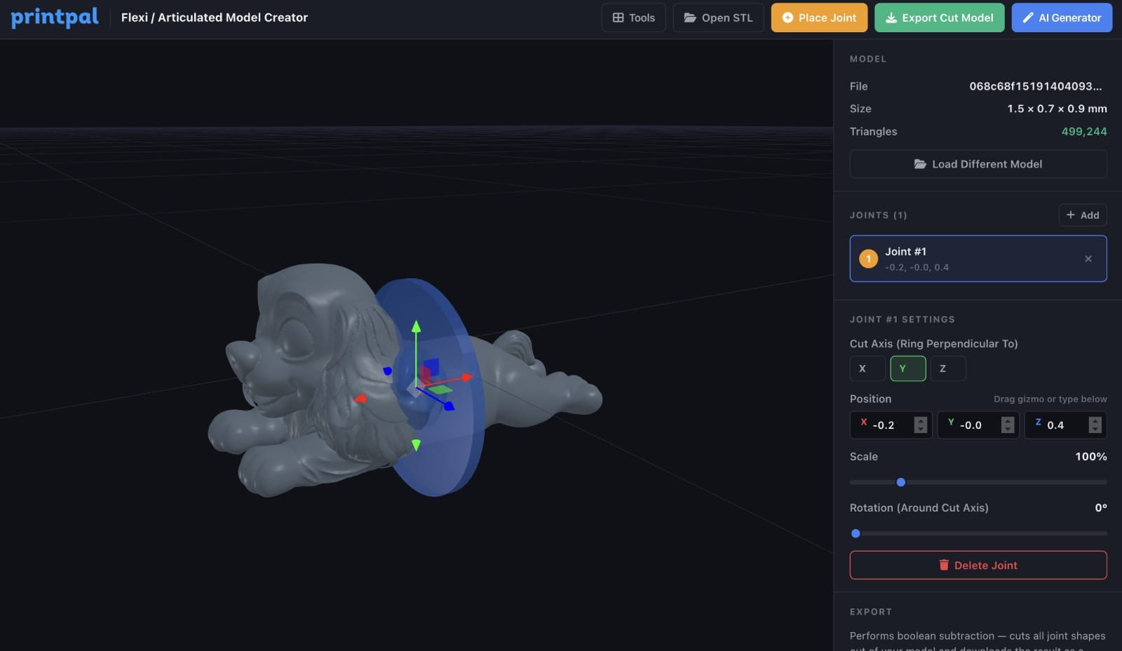
Each joint has an axis setting that determines the direction of the cut. You can choose X, Y, or Z using the axis buttons in the sidebar. The cut axis controls how the ring-shaped cutter is oriented. Think of it this way: the ring sits perpendicular to the chosen axis. If your model is a snake lying along the X axis, you would choose X so the cuts go across the body. If you are not sure which axis to use, try each one and watch how the cutter rotates in the 3D viewer. You can change it at any time.
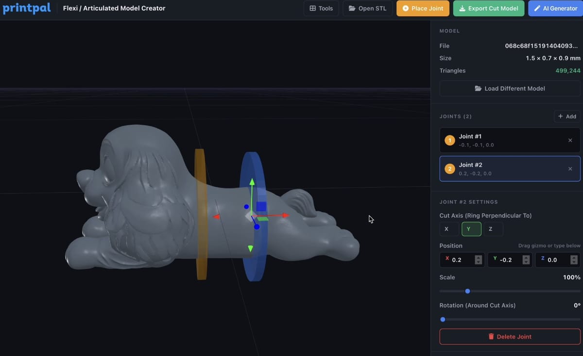
Step 5: Adjust Position, Scale, and Rotation
Once a joint is placed, you can fine-tune it using the sidebar controls or by dragging the 3D transform gizmo directly in the viewer.
Position - Use the X, Y, Z sliders in the sidebar or drag the colored arrows on the gizmo to move the joint along any axis. The gizmo arrows are red (X), green (Y), and blue (Z).
Scale - Adjust the scale slider to make the cutter larger or smaller. The cutter should be slightly larger than the cross-section of the model at the cut point. If it is too small, the boolean cut will not go all the way through. If it is too large, it will remove more material than needed.
Rotation - Use the rotation slider for fine angular adjustments around the cut axis. The 3D viewer updates in real time as you make changes, so you can see exactly what the cut will look like.
Step 6: Place Additional Joints
Click "Place Joint" again to add more joints. Each new joint inherits the axis, scale, and orientation of the previous joint, so you do not need to reconfigure every one from scratch. For a typical flexi animal or dragon, you might place 8 to 15 joints along the spine. For a simple fidget toy, 1 to 3 joints may be enough. Each joint appears in the sidebar list. Click on any joint in the list to select it and adjust its settings individually.
Step 7: Review Your Joints
Before exporting, orbit around your model and check each joint placement. Things to look for:
- Each cutter ring fully intersects the model (no gaps where the cut would not go through)
- Joints are spaced evenly enough that each segment can flex without colliding with its neighbors
- The cutter is oriented correctly so the joint allows movement in the direction you want
- No two cutters overlap each other
You can select any joint in the sidebar list to re-adjust or delete it.
Step 8: Export the Cut Model
Click the "Export Cut Model" button at the bottom of the sidebar. The tool performs boolean subtraction using a Web-based geometry engine. Each cutter is subtracted from the model in sequence. This process takes a few seconds depending on the complexity of your model and the number of joints. A progress indicator shows which joint is being processed. Once complete, your browser downloads an STL file of the model with all the joint cuts applied. This is the file you will print.
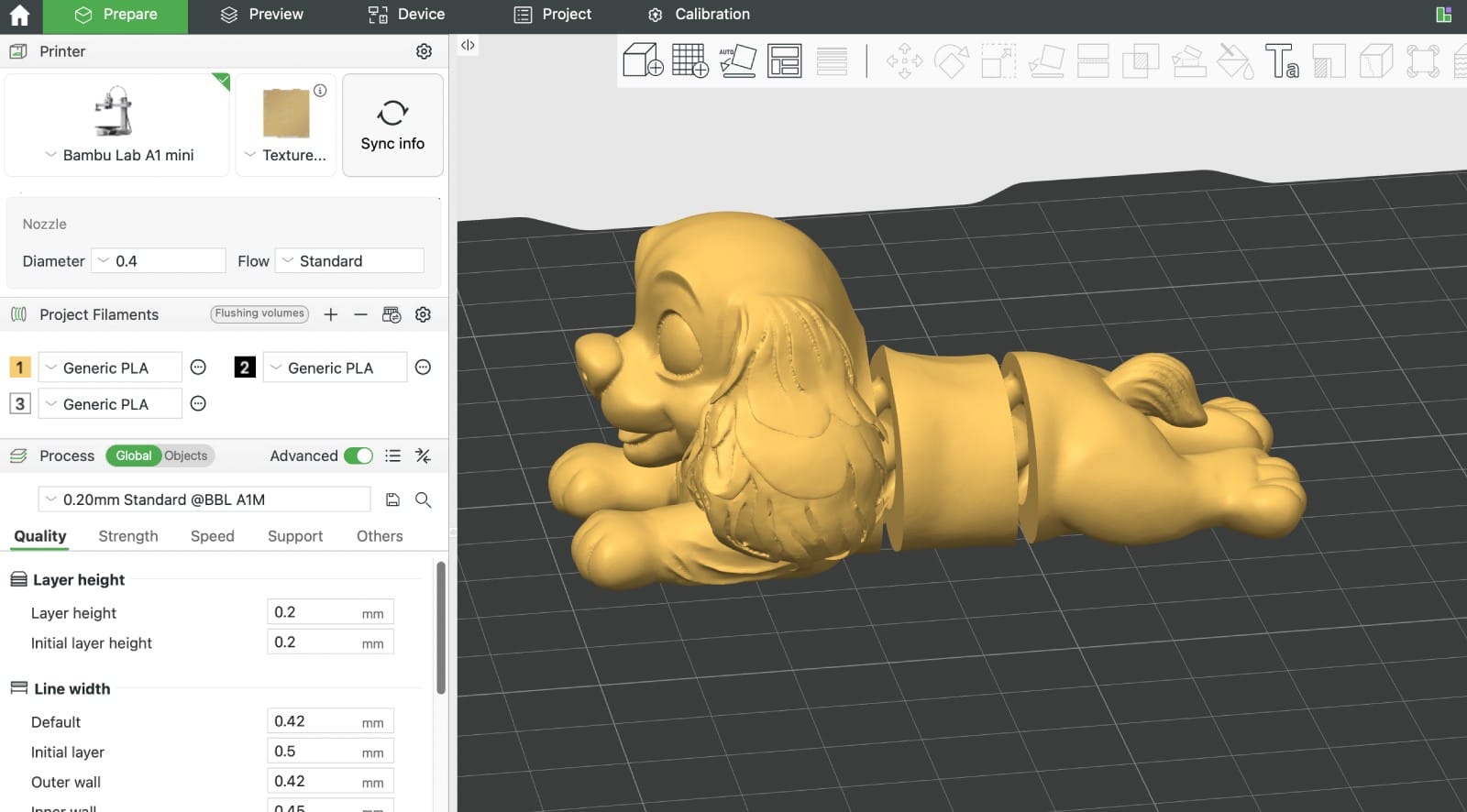
Step 9: Prepare for Printing
Open the exported STL in your slicer. You will notice the cut channels where each joint was placed. These channels are where the flexi joint geometry sits.
For best results:
Layer height - Use 0.2mm or lower. Thinner layers produce smoother joint movement.
Print orientation - Print the model in its natural orientation. The joints are designed to work with standard layer-by-layer printing.
Supports - Depending on the model geometry, you may need supports in some areas. The joint channels themselves typically do not need supports if the cutter was oriented correctly.
Material - PLA works well for most flexi prints. PETG and TPU also work but may require different temperature and speed settings.
Infill - 15 to 20 percent is usually sufficient. The joint areas are thin enough that infill density does not significantly affect flexibility.
Common Questions
Does the tool create the joint inserts too?The tool creates the cuts in your model where joints will go. The actual joint geometry (the snap-fit connectors) should be printed separately using standard flexi joint STL files, which are widely available for free.What if the export fails?Boolean operations can fail on non-manifold geometry. If you get an error, try repairing your mesh using a tool like Meshmixer or the built-in repair in your slicer before uploading.Can I undo a joint placement?Yes. Select the joint in the sidebar list and click the delete button to remove it.Is there a limit on how many joints I can place?There is no hard limit. However, more joints means longer export times and a more complex final mesh. For most models, 5 to 20 joints is the practical range.Do I need a subscription?The tool is free to explore and use. Exporting the cut model requires an active Pro or Studio subscription.
Start Making Flexi Prints
Turn any rigid 3D model into a posable, articulated print in minutes. No CAD experience needed.Try the Flexi Model Creator
Have feedback or feature requests? Join our Discord and let us know.